experimental manned space aircraft
Item 105-11 is a flight-capable version of experimental manned space aircraft (EMSA, EPOS in Russian) which was under development in Mikoyan design bureau as a part of the Spiral programme (object #50, later – object #105-205) approved and ordered for implementation by the Ministry of Aircraft Industry in July 30, 1965. In late 1965, the Communist Party’s Central Committee and the USSR Council of Ministers issued a resolution concerning the development of the Aerial-Orbital System (VOS in Russian): the Spiral experimental complex of the manned space aircraft included a shuttle space aircraft (item 105) and shuttle launcher aircraft (item 205) intended for the orbit shot of the shuttle. The Tupolev-developed hypersonic booster aircraft (HBA) was supposed to accelerate the aerospaceplane to Mach 6, after which the VOS aerospaceplane would be launched off the HBA to be delivered to orbit by a booster rocket.

First, a decision was made to develop an experimental manned aerospaceplane designated EPOS that would have been launched to the orbit by the R-7 rocket. For re-entry and pre-landing manoeuvres, item 105, unlike landing modules of conventional spacecraft, had an aircraft architecture, namely – tailless load-bearing fuselage with low-mounted delta wing whose wing panels were turned upwards, vertical control surfaces and standard controls (ailerons, rudder), landing gear and traditional “aircraft” turbojet engine RD36-35K producing 2,000 kgf thrust. For aircraft control at hypersonic and supersonic speeds in orbit and atmosphere the shuttle had gas-dynamic control modules (compact liquid-propellant engines combined into two units, each containing three nozzles producing 16 kgf thrust and five nozzles producing 1 kgf thrust) while for manoeuvre in orbit or during re-entry the aircraft had liquid-propellant engine with 1,500 kgf thrust and two additional chambers, each producing 40 kgf thrust.
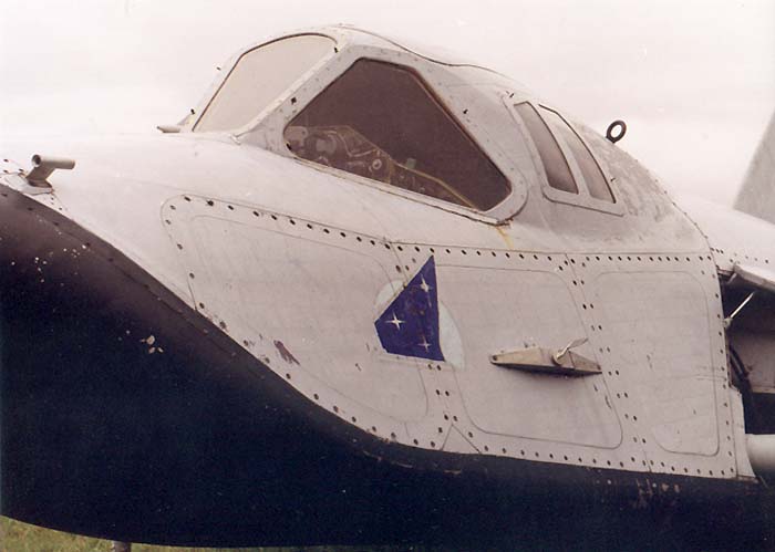
All engines were located in the aft of the fuselage. To protect the fuselage against thermodynamic overheat during re-entry, a steel heat-resistant shield was provided. The cockpit was made of steel with heat insulation coating in a form of a rescueable pressurised capsule which could be blasted off in case of emergency.
Development of the preliminary design for the Spiral project commenced in 1965, in 1966 preparation of conceptual design started. At the same time in 1966 a decision was made to build item 105-11, an analogue of the EMSA (with turbojet engine but without gas-dynamic controls) for atmospheric tests of the aircraft at subsonic speeds which was to be launched from aboard Tu-95KM appropriately refitted to serve the purpose. Development of the mentioned above analogue started in 1968 and at the same time, on the Kuybyshev (nowadays Samara) Aircraft Plant refitting of the Tu-95KM bomber # 2667 allocated by the Air Force into experimental shuttle launcher was initiated. It was expected that later on the testing program would be joined by two other analogues of the EMSA – item 105-12 and 105-13, both with liquid-propellant engines and capable of supersonic and hypersonic speeds respectively.
In order to test RD36-35K jet engine starting at high altitudes a special flying laboratory L-18, based on K-10S missile and Tu-16K-10 bomber as a launcher aircraft was developed.
The programme’s general guidance was performed by G.Ye. Lozino-Lozinsky. In 1970 all work regarding development of the EMSA analogues were dismissed from the Zenith Mechanical Plant and assigned to the Raduga Mechanical Plant in Dubna. To run the programme, a 150-strong team was set up having been manned by the Dubna affiliate with the OKB-155-1 having branched off and turned into an independent
Raduga organisation. In 1971 assembly work of the aircraft 105-11 # 1-01 was completed in the Raduga Plant. In 1972 manufacture of the 105-12 analogue and assembling of experimental batch (5 items) of “0” series products (# 001 – 005) was launched. Aircraft # 001 was intended for static tests, # 002 – for life saving equipment testing, # 003 and # 004 – for optimisation of the liquid propellant engines and gas-dynamic controls, # 005 – for heat resistance and material strength testing. Aircraft # 002 was ready for tests in 1971, # 005 – in 1973, # 001 and # 003 – in 1974.

Besides, in 1971 testing program carried out under the Spiral project was joined by scale 1:3 and 1:2 EMSA models manufactured by LII Institute and code-named Bor.
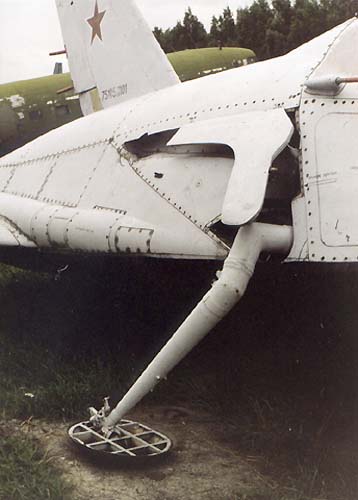
Assembling of the 105-11 analogue was completed in 1974 and in 1975 this aircraft was moved to the Science and Research Institute of the Air Force in Ahktubinsk where pre-flight preparations of the aircraft began. The 105-11 analogue was equipped with wheel-base landing gear (instead of standard ski gear). In 1976 the aircraft made 15 test runs and 10 hops ( for the first time – in July 20). Finally, in October 11, 1976, Aviard Fastovets, a test pilot of the Mikoyan Mechanical Plant, took the 105-11 aircraft for the first flight and flied from one unpaved airfield to the other. 19 km long flight was maintained at 560 m above the ground level. In 1977 the Institute proceeded with flight tests with the aircraft including launching from aboard the Tu-95KM. The first airborne disengagement from the Tu-95KM launcher at the altitude of 5,000 m, controlled flight with powered turbojet engine and airfield landing was accomplished by Fastovets on October 27, 1977. Total amount of similar flights is 8.
In order to proceed to the second stage of the testing program, a wheel-based landing gear of the aircraft was replaced with ski gear.
In 1978 flight tests of item 105-11 at subsonic speeds intended to establish aircraft performance during disengagement from the launcher came to the end. During the last test flight in 1978 the aircraft suffered some damage during landing. By the end of the tests, an independent Molniya design bureau had been established, which immediately joined the programme. In 1976 the USSR started a Buran Space Aircraft Programme aimed at the development of the conceptually new aircraft. By 1979 any work related to the Spiral Project and item 105 were terminated. Nevertheless, all efforts and experience gathered when working on the Spiral project was not in vain and was widely used when developing Energy-Buran multipurpose spacecraft system, the first time (unfortunately, at the same time it was the last start) launched in November 15, 1988.

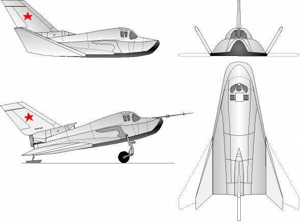
Airframe configuration and design: the space aircraft was built using tailless scheme with load-bearing airframe, low-mounted delta wing, single-fin tail unit, single aft-located engine and four-wheel landing gear. The load-bearing fuselage in planform view is arrow-shaped (78o sweep angle). Cross-section of the fuselage has rounded upper part and virtually flat bottom. The fuselage is comprised of 4 segments: 1) nose equipment section and cockpit, 2) framework with longerons and main frames, 3) sheathing panels with air intakes for turbojet engine, 4) bottom heat-resistant shield.
The framework is considered the main part of the fuselage. The framework with longerons and frames is a welded three-dimensional load-bearing structure made of VNS-2 steel. The framework scheme was selected in order to provide maximum space for installation of engine, fuel tanks and equipment and ensure minimal heat stresses. The lower mid-section of the fuselage is used for a fuel tank-compartment which is an integral part of the load-bearing frame. The aft section of the fuselage contains the turbojet engine. Air intake of this engine has shutters operable in the “engine on” mode. Nose section containing cockpit and equipment is a standard welded structure made of VNS-2 sheet steel bolted to the framework with explosive bolts, thus creating a rescueable capsule. Panels and air intake of the turbojet engine are standard structural elements made of duralumin. The panels intended to cover the framework are bolted to it.
The heat resistant shield is installed in the bottom of the framework and provides framework protection against thermodynamic heat. In addition, the shield composes the main load-bearing surface of the fuselage. The shield is a welded structure made of VNS-2 sheet steel with a set of contact-welded shapes, angles and bars. Inner side of the shield has a heat insulating coating. Shield mounting on the framework is provided through 110 free-oriented holders. In case of non-uniform heating such approach ensures expansion/contraction movement of the shield in all directions without heat stresses. Detachable panels include escape hatch, equipment and engine access doors and side panels.
The outer wings have 55o sweepback angle at the leading edge. Outer wings are attached to the fuselage but can be tilted upward by 30o depending on the flight mode. Wing tilting is provided through electric drive with worm gearing. For in-flight roll control the wing is supplied with ailerons. Vertical control surfaces include rudder and 1.7 m2 fin with 60o sweepback angle at the leading edge. The upper surface of the fuselage aft portion contain balancing upward-extendable flaps. The space aircraft has a flight control system typical of conventional aircraft – pedals and manually operated sticks and levers.
The aircraft has a four-foot, retractable ski landing gear (for taking off the ground, the front struts were fitted with wheels early in the flight testing). The nose landing gear is retracted by turning backward into compartments in the side panels of the fuselage above the heat resistant shield. Landing gear extension is actuated by pneumatic system.
Power plant of the 105-11 aircraft consists of RD36-35K engine producing 2,000 kgf thrust. Fuel tanks for the turbojet engine are located in the middle section of the fuselage.
Avionics include a standard set of navigational instruments, indicators and devices, situated on the pilot’s console in the cockpit.
| Description | ||
|---|---|---|
| Design | OKB A.I.Mikoyan | |
| Type | 105 | 105.11 |
| Function | experimental manned space aircraft |
EPOS |
| Crew | 1 | 1 |
| Dimensions & Weight | ||
| Length, m | 8 | 8,5 |
| Wing Span, m | 7,7 | 6,4 (7,4) |
| Basic Diameter, m | 2,8 | |
| Heght, m | 3,3 | 3,5 |
| Take-off weight, kg | 10300 | 4220 |
| Power-plant | ||
| atmosphere | ||
| Engines | turbojet RD-36-35K | turbojet RD-36-35K |
| Thrust, kgf (kN) | 2350 | 2000 |
| orbital | ||
| Engines | rocket | |
| Thrust, kgf (kN) | 1х 1500 & 2х 40 | |
| reaction control system (GDU) | ||
| Engines | rocket | |
| Thrust, kgf (kN) | 6x 16 &10x 1 | |

References and Credits:
- History and aircraft of Mikoyan design bureau / «Wings of Russia», 1999, CD-ROM /
- Aerospace system a SPIRAL: details / BURAN.RU /
- In space on wings. Техника Молодежи №1′ 199?
- My heavenly life / V.Menitskiy, Moscow, 1999 /
- Encyclopedia Astronautica / M.Wade /
- The encyclopedia «Cosmonautics». A.B.Zheleznyakov